Choosing Between PCB and Cable RF Connectors: Key Differences and Use Cases
RF PCB Connectors and RF Cable Connectors remain fundamental components in radio-frequency systems where stable signal integrity, controlled impedance, and mechanical reliability are mandatory. Much of the confusion between these connector families comes from their overlapping roles in modern designs, yet each category serves distinct engineering needs. This article offers a professional overview intended for procurement specialists and engineering teams working in high-frequency applications. The discussion explores how both connector types function, what differentiates them, and how to make informed decisions when selecting the correct interface for a project. It also incorporates related topics such as Understanding RF Connectors: An Introduction, Overview of PCB RF Connectors, Overview of Cable RF Connectors, and other essential considerations.
Understanding RF Connectors: An Introduction
Every system that carries radio-frequency energy depends on a stable transition between circuit elements, which is why connectors play such a crucial role. Designers evaluate characteristics such as impedance stability, insertion loss, and frequency range long before selecting any interface. When comparing RF PCB Connectors with RF Cable Connectors, it becomes clear that each type is designed for a different physical environment. Engineers consider factors such as mounting method, mechanical load, cable routing, and environmental exposure. Teams responsible for procurement also assess manufacturing consistency, reliability records, and certification requirements. Reliable sources like IEEE provide foundational standards that guide these evaluations. These standards help ensure that connector selections align with long-term product performance goals.
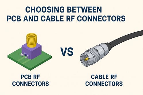
Overview of PCB RF Connectors
Interfaces designed for direct mounting on printed circuit boards follow strict mechanical and electrical rules. RF PCB Connectors normally operate with short transmission paths, enabling efficient signal handling at high frequencies. Their compact structure fits into dense layouts, which is essential in today’s embedded systems. Because they attach firmly to board lands, these parts reduce flexing and preserve alignment in vibration-heavy environments. Many engineers choose them for devices where weight and size matter. They often appear in products such as handheld terminals, compact sensors, and modules with integrated antennas. The design approach limits signal exposure to interference, so consistent high-frequency behavior becomes easier to maintain. This fixed installation also simplifies assembly processes and improves repeatability in manufacturing.
Use Cases for PCB RF Connectors
Applications relying on embedded circuitry often benefit from these compact interfaces. Typical uses include RF modules, wireless communication boards, IoT devices, and lightweight industrial equipment. Systems requiring precise tuning or short signal paths frequently depend on these connectors. Because of their robust mounting style, many portable devices adopt them to achieve repeatable impedance across wide frequency ranges. Scenarios involving automated assembly also favor board-mounted solutions.
Overview of Cable RF Connectors
Designers seeking flexibility in routing or the ability to separate modules often turn to RF Cable Connectors. This family accommodates a broad range of cable types, offering distances and movement that board-mounted connectors cannot provide. They allow straightforward field replacements where maintenance teams require access to cabling without disturbing PCBs. These interfaces also tolerate mechanical shifting better than rigid-mounted parts. Their structure supports varied environmental conditions, making them ideal for networks, instrumentation, and installations where cables must run across enclosures. Engineers utilize them when a design demands both mobility and high-frequency stability.
Use Cases for Cable RF Connectors
Many communication infrastructures rely heavily on connectors designed for flexible cabling. Industries such as aerospace, automotive testing, laboratory instrumentation, and telecommunications routinely specify these parts due to their field-service capability. When equipment operates across multiple subsystems or requires interchangeable modules, cable-based links provide practical advantages. These connectors also support remote antennas where long distances separate radiating components from the main board.
Key Differences Between PCB and Cable RF Connectors

Comparing these two connector categories reveals several clear distinctions. First, RF PCB Connectors offer fixed positioning that supports predictable electrical paths. In contrast, RF Cable Connectors enable extended routing where movement or distance becomes essential. Second, PCB options reduce the number of mechanical interfaces, which lowers insertion loss in compact systems. Cable-based solutions, meanwhile, deliver adaptability that helps designers reconfigure layouts without redesigning the entire board. Third, board-mounted interfaces excel in miniaturized products, while cable-based alternatives excel in modular systems where panels, housings, or subassemblies require frequent rearrangement. Understanding these structural differences helps engineering teams shorten evaluation cycles and reduce project risks.
Performance Considerations for Each Connector
Performance requirements dictate which connector type suits a specific RF environment. In high-frequency sectors, minimizing losses is essential. RF PCB Connectors achieve stability because of their short electrical paths and consistent mechanical alignment. Meanwhile, RF Cable Connectors support greater flexibility at the expense of slightly increased insertion loss due to longer cable distances. Designers also factor in shielding effectiveness, return loss characteristics, and frequency compliance. Systems operating above several gigahertz may emphasize board-mounted options to maintain low impedance deviation. However, cable-based connectors remain indispensable where the physical layout requires movement or spacing. Industry specifications often recommend verifying each connector choice through vector network analyzer measurements and environmental stress tests.
Environmental Factors to Consider
Environmental conditions influence connector selection as much as electrical performance. Designs exposed to temperature swings, moisture, vibration, or continuous motion must consider mechanical durability. For instance, RF Cable Connectors provide strain relief when equipment undergoes frequent repositioning. Conversely, RF PCB Connectors minimize the risks associated with loose cables by maintaining a compact and protected interface. Engineers also evaluate compliance with standards for dust ingress or electromagnetic shielding. In rugged installations such as outdoor units or industrial enclosures, cable options often deliver superior maintainability. Understanding these environmental pressures ensures that procurement teams align component choices with real-world operational demands.
Making the Right Choice for Your Project
Selecting the correct interface requires analyzing priorities such as size constraints, mechanical load, serviceability, and frequency performance. When teams prioritize compact layouts or consistent electrical behavior, RF PCB Connectors often deliver better advantages. When long distances, modularity, or field adjustments are central to the design, RF Cable Connectors become the more practical alternative. Project requirements shape this decision, making early collaboration among engineering, procurement, and manufacturing teams essential.
Choosing the Best Connector Type
Determining the most suitable connector comes down to weighing the trade-offs between mechanical stability and system flexibility. Solutions that integrate the board and RF path tightly require connectors that lock directly onto the PCB — such as Kinghelm’s RF PCB Connectors. Systems that branch into distributed modules or need extended cable runs rely on cable-based interfaces — such as Kinghelm’s RF Cable Connectors. By understanding these differences, teams choosing between the two options can balance cost, reliability, and long-term performance. Thoughtful evaluation ultimately ensures that RF behavior remains stable throughout the product lifecycle.


Comments
Post a Comment